

Understanding Optocoupler Failure in Industrial I/O Modules
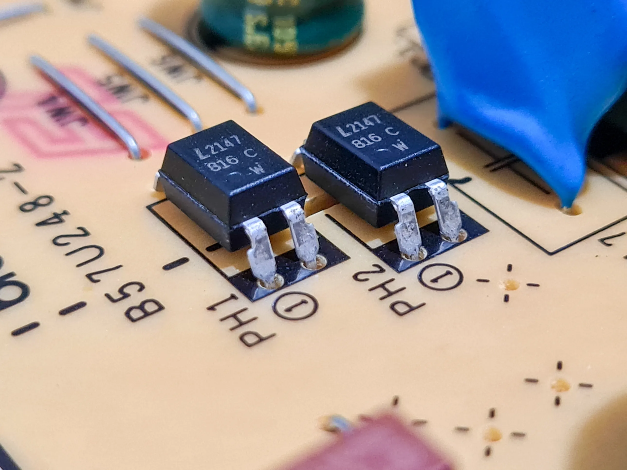
Between the terminal block where field wiring lands and the circuitry that reports an input’s state, many I/O modules pass each signal across a small gap as light. The part that does it is an optocoupler: an LED and a light sensor sealed in one package with nothing conductive between them. That gap is the point. It keeps field voltage, transients, and ground loops on the field side while the signal crosses to the logic side.
How it works
When a field device switches on, current flows through the optocoupler’s LED, and it lights. The light crosses an insulating gap inside the package and strikes a phototransistor on the logic side, which conducts and tells the module the input is on. When the field device switches off, the LED goes dark, and the phototransistor stops conducting. The two sides never touch. Isolation ratings run from a few thousand volts to as much as 10,000 volts, depending on how the part is built.
Isolated outputs can work the same way in reverse, with the logic side lighting the LED, and the field side switching the load. The failure patterns below apply to both, though they’re easiest to picture on an input.
Two ways it fails
An optocoupler can fail slowly or all at once. The slow failure is the LED dimming with age. Every LED loses light output over time. Heat and higher drive current speed up the process. A dimmer LED hands a weaker signal to the phototransistor.
Most optocoupler LEDs lose only a little over decades of normal service, but individual parts vary. An LED that runs hot degrades much faster. The phototransistor needs a certain amount of light to switch reliably. As the LED dims, the margin above that threshold shrinks. A hot enclosure is often what finally pushes a weak channel under it.
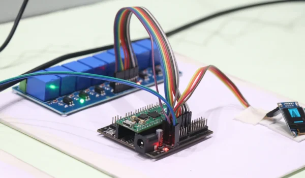
The sudden failure comes from overdriving the part. Voltage beyond the input’s rating, reverse polarity on a DC input, or a transient bigger than the isolation barrier was built for can burn out the LED or break down the barrier. A barrier failure is the worse of the two, since it can carry field voltage into the logic circuitry it was supposed to protect.
How it shows up on the floor
Each failure leaves a different trail:
- A channel stuck on or off, no matter what the field device does, which is a sign of a burned-out optocoupler
- An input that drops out only when the enclosure runs hot, where a dimming LED no longer has margin to spare
- One dead channel on a module where every other channel still works
- A false “on” from a healthy optocoupler, when leakage current from a two-wire sensor is enough to light the LED
That last one belongs on the list because it sends people after the wrong part. Leakage is a field-side problem, and replacing the module won’t clear it.
One channel, one part
When each channel has its own optocoupler, a failure usually stays confined to that channel. A module with one dead input still has a working power section, a working backplane interface, and every other channel intact. That makes a strong case for component-level repair over replacing the module outright, as long as whatever overdrove the part gets discovered first.
An input channel that’s stuck or drops out in the heat doesn’t have to mean a new module. Global Electronic Services repairs PLC and I/O modules at the component level, down to the individual channel that failed. Contact us for Repair, Sales & Service of Industrial Electronics, Servo Motors, AC & DC Motors, Hydraulics & Pneumatics — don’t forget to like and follow us on Facebook, LinkedIn, YouTube, and X!
