Repair Processes
- AC/DC Drive Repair
- Chart Recorder Repair
- Circuit Breakers Repair
- CNC Controls Repair
- Counters and Timers Repair
- Encoder Repair
- Flow Meter Repair
- Input and Output Modules Repair
- Industrial Controls Repair
- Industrial Monitors Repair
- PLCs Repair
- Power Supplies Repair
- Printed Circuit Boards Repair
- Robotics Repair
- Safety Equipment Repair
- Servo Drives Repair
- Soft Starts Repair
- Spindle Drives Repair
AC/DC Drive Repair Process:
To begin the repair on an AC/DC drive a visual inspection is performed.
- Next meters and signature analysis devices are used to component test.
- Common failure parts such as capacitors, drive and output transistors, power supplies, SCR’s, and firing circuits are checked first.
- Common failure parts are tested and replaced as necessary
- Drive is then powered up
- While powered up the power supplies are checked as are the outputs for proper wave form
- A dummy load is applied to the drive and the output waveform is checked with an oscilloscope
- If proper output is seen the dummy load is removed and the drive is fully load tested with the proper motor and with a dynamometer
- It is scoped again for proper wave form
- Entire unit is cleaned and retested
Chart Recorder Repair Process:
Each chart recorder is first disassembled and visually inspected for any obvious damage.
- The batteries are tested as are all the power components and fuses
- Units are inspected for any loose connections
- Next step in repairing the chart recorder is to power the unit up and trouble shoot to component level
- Repairs are made and components are replaced as necessary
- Repairs are supplied with input power, the inputs and outputs are checked, the control circuits and micro controllers are also inspected
- The unit is set to the factory defaults input signals such as 4-10 ma , a thermocouple, RTD, or a pressure transducer
- Verify the output on the chart to ensure it is within manufacturers specifications
- Entire unit is cleaned and retested
Circuit Breakers Repair Process:
Circuit breaker repair is begun by putting the unit in the on position and checking for the proper closure for contacts.
- A regulated high current is applied to the circuit breaker to actually trip mechanisms and measure trip timing
- Adjustments to the magnetic trips throughout ranges are made and the shunt trips are tested
- The contacts are replaced, as necessary, as are the trip mechanisms
- Entire unit is cleaned and retested
CNC Controls Repair Process:
All units begin with visual inspection of all connectors, operator controls, printed circuit boards, and displays when applicable.
- Common failure components such as switches, potentiometers, capacitors, and diodes are tested using DMM’s, LCR’s Huntron Tracker and capacitor/inductor analyzers for functionality and tolerances
- Repairs are made as necessary
- Power is applied
- All supply voltages are checked according to OEM load specifications
- Test signals are applied to test all inputs/outputs for proper operation
- Repairs are then made if necessary
- Unit is then cleaned retested before shipping
Counters and Timers Repair Process:
Counters and Timers are visually inspected for broken and missing parts.
Mechanical Timers:
- Verify the mechanism
- Replace relays (as they are a common failure component) as necessary
- Align and adjust the mechanics
- Verify the unit keeps proper time and that it actuates correctly
Electric Timers:
- Verify that the oscillator is the correct frequency and that the input and outputs are functional
- Check for tightness of mechanical contacts
Counters:
- Verify the logic functions in all modes of the counter
- Power supplies are tested
- A signal generator is used to verify proper count
Encoder Repair Process:
To begin the repair of an encoder, the gratical is first visually inspected for damage.
- After the gratical is determined to be good the shaft is rotated and stressed to test bearings
- Power is applied and a rotational test is performed
- The shaft is rotated to specified RPM’s
- All signals/pulse/counts are verified to OEM specifications
- Defective components are identified and replaced
- Entire unit is cleaned and retested
Flow Meter Repair Process:
- Visual inspection is made of all mechanical parts
- Sensor wheel is checked for worn or damaged parts, and is free to spin
- All circuitry is tested for damaged or shorted components
- Repairs are made as necessary
- Power is then applied to unit and flow is simulated
- Outputs are then tested and set points verified
- All transmitters are tested for proper signal strength and data content
- Repairs and adjustments are made as necessary
- Entire unit is cleaned and retested
Input and Output Modules Repair Process:
OEM specific test stations are used to test I/O modules.
- Modules are placed into test stations to identify problems
- Power supplies are checked and components are replaced as necessary
- All inputs and outputs are verified
- The ladder logic is verified with a test program
- The sink and source current is verified
- All high failure rate components such as driver IC’s and transistors (on output modules) and opto’s (on input modules), capacitors and transients are checked for proper operation
- Entire unit is cleaned and retested
Industrial Controls Repair Process:
A visual inspection is first performed and power and output components are checked.
- All high failure component such as capacitors, transistors, and MOV’s are checked
- Power is applied and all internal power supplies are checked
- All outputs such as mechanical, solid state relays, transistors are load checked
- All software is verified to be functional upon booting
- A small test program is run and exercised to verify the repair
- Entire unit is cleaned and retested
Industrial Monitors Repair Process:
CRT Based
To perform the repair of a CRT based industrial monitor the power supply is first checked.
- Next the horizontal circuit is checked for shorts
- A visual check of the flyback and deflection yolk is performed
- After the video parameters from the OEM are programmed into the monitor analyzer, the industrial monitor is then powered up and checked for B, horizontal and vertical frequencies
- An input signal is applied
- A check for vertical and horizontal alignment and convergence is performed; as well as white balance and regulation, and color purity
- All high failure rate components such as capacitors and horizontal outputs are replaced as necessary
- The G2 and focus voltages are set and the unit is cleaned
LCD Based
To perform the repair of an LCD based industrial monitor all high failure rate components are checked such as power supplies, capacitors, inverters, backlights, and LCD’s.
- The backlights are checked for color temperature
- The white balance is checked on the LCD
- The backlight inverter is checked for proper output voltage
- Vertical and horizontal alignment is checked as well as the pixels in the LCD
- The monitor unit is hooked to a CM2000 Analyzer
- OEM specifications are verified during final test
- Entire unit is cleaned and retested
PLC’s Repair Process:
A visual inspection is performed on all PLC’s to start the repair.
- Input power is then applied and the inputs and outputs are checked
- Capacitors, opto isolators, relays, and other common failure rate components are checked and replaced as necessary.
- A small test program is installed to verify the CPU and logic are functioning correctly
- The ladder logic and battery backup are also tested as well as the circuit
- Entire unit is cleaned and retested
Power Supplies Repair Process:
A visual inspection is first performed on all power supplies to start the repair
- Next a check is done on the input circuit- the bridge, the capacitors, the rectifier, the switches and the fuses before power is applied
- Repairs are made as necessary
- Input power is applied to verify the output voltages and regulation
- If the power supply has a sense circuit it is verified for proper operation
- All output voltages are verified under full load conditions
- 2000 Analyzer and OEM specifications are verified during final test
- Entire unit is cleaned and retested
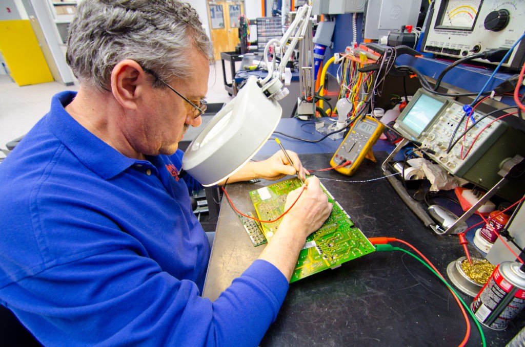
Printed Circuit Boards Repair Process:
A visual inspection is the first step in the repair of PCB’s, to find missing or damaged components or blown traces.
- A Huntron Tracker as well as LCR’s , Digital Multi-Meters, Z meters, capacitor and inductor analyzer are used to test all components and traces
- Any component found out of tolerance is replaced
- Boards are powered up and tested for functionality and tested in an application when possible
- Boards are cleaned and recoated when necessary and placed in an anti-static bag to prepare for shipment.
Robotics Repair Process:
All systems are inspected first for surface defects and physical/mechanical damage
- Repairs are made as necessary
- All electromechanical assemblies are tested using LCR’s, Oscilloscopes, DMM’s and capacitive/inductor analyzers
- Repairs and replacements of components are completed
- All circuit board including common failure components are fully tested, such as capacitors, relays, diodes and switches
- Front panels are refurbished as necessary, including video displays, output controls, pushbuttons, and potentiometers
- Cables, interface boards, cooling fans will be inspected and serviced as needed
- Power supplies are loaded to OEM recommendations, then restored to OEM specifications
- Included in our final stages of service, is full power-up of all systems, burn in cycling, output verifications and load testing
- Entire unit is cleaned and retested
Safety Equipment Repair Process:
Light Curtains
- Visually verify lenses for chips or deep scratches
- check connectors for broken or bent pins
- Polish lenses
- Test with a universal tester to verify signals and/or transmission
- Entire unit is cleaned and retested
Scanners
- Visually verify lenses for chips or deep scratches
- Check connections for bent or broken pins
- To confirm proper operation, the motor is checked and the scanner is hooked up to a computer to verify communication and run manufacturer diagnostics
- Repairs are made as necessary to correct problems
- The scanning mirror is cleaned
- The optical alignment is verified
- All alarm outputs are checked
- The unit is cleaned
Servo Drives Repair Process
The servo drives are visually inspected for broken and missing parts and standoffs or bent hardware.
- The mosfets, IGBT’s relays, inputs, outputs, feedback circuits, and power supplies are all checked before power is applied to the unit
- After parts are replaced or repaired, the servo drive is hooked up to a universal tester to verify feedback, proper phase, rotation and direction underload.
- Entire unit is cleaned and retested
Soft Starts Repair Process:
Visual checks are done on soft starts to begin repair.
- Before applying power the SCR’s, gates, and power supplies (when applicable) are checked
- Next, 3 phase power and control voltage are supplied to the soft start
- A load such as a resistor bank, capacitor bank, or motor is applied to test for full functionality
- During this full test , the current limit, timing curve, and operation of the bypass contractor are all checked
- Entire unit is cleaned and retested
Spindle Drives Repair Process:
Every unit is given our highest level of services. These drives are inspected for surface defects and shorted components.
- All common failure components are tested and replaced as necessary
- Special test stands are used in conjunction with full dynamometer loading to test not only load capabilities, but to eliminate ripple and velocity errors that can actually leave their mark on work pieces
- Before leaving, these units are calibrated to deliver smooth running and accurate control.
- Entire unit is cleaned and retested
Normal Repair Turnaround Time and Emergency Service
At Global Electronic Services, we will get your facility up and running with reasonable rates in the quickest time possible.
- Fast 3-5 Day Turnaround
- Rush Service Available
- Same Day- Down Situation depending on parts stock
- Emergency after hours repair is available for an additional 25% of the repair cost or $250.00 whichever is greater
Call Global Electronic Services when your facility faces temporary shutdown because of an emergency repair:
- Troubleshooting help
- Sending a rush repair
- Choosing from our vast inventory of surplus equipment
Our emergency repair line is staffed by our highly trained representatives and is available to take the call 24 hours a day 365 days a year for:
Emergency after hours repair is available for an additional 25% of the repair cost or $250.00 whichever is greater.
Additional Resources:
- Difference Between AC and DC
- Fanuc CNC Troubleshooting
- Common Servo Motor Problems and How to Resolve Them
- Servo Motor Drive Troubleshooting Guide
- Servo Motor Repair Steps
Why Choose Us
-

-

-

-

-

-
Key Responsibilities
- Reduces long turnaround times
- Communicates during the entire process
- Utilizes our in-house repair facility to replace the high mark up and low value of our competitors with our single source system to provide maximum speed and value to our customers
Some Items We Repair
Our returning customer rate is over 98% since we started and our goal is 110% customer satisfaction.
When you call, we will be happy to help you find the fastest, most affordable solution!