Testing Servo Motor Performance Using Oscilloscopes
Servo motors are the backbone of precision in countless industrial applications. But to keep these motors running smoothly and reliably, rigorous testing is nonnegotiable. Enter the oscilloscope: a test engineer’s go-to tool for unlocking deep insights into a servo motor’s performance.
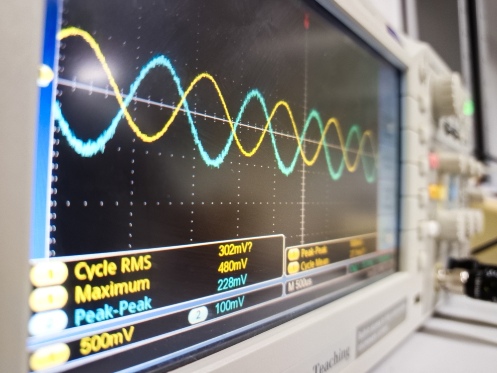
Oscilloscopes provide real-time visualization of electrical signals, allowing engineers to observe and analyze motor behavior as it happens. With high-resolution measurements of voltage and current, they enable precise quantification of servo motor parameters. Their ability to capture and analyze transient events is crucial for identifying intermittent issues or performance anomalies.

Key parameters to measure
- Current Waveform: The current waveform provides insights into the motor’s power consumption and efficiency. A clean (sinusoidal) waveform typically indicates good motor health, while distortions may suggest bearing wear or winding issues.
- Back EMF: Back electromotive force (EMF) is generated when the motor shaft rotates. Measuring back EMF can help assess the motor’s mechanical condition and detect issues like demagnetization.
- Commutation Signals: For brushless DC motors, analyzing commutation signals helps verify proper timing and sequencing of the motor phases.
- Position Feedback: Encoder or resolver signals can be monitored to evaluate the accuracy and resolution of the motor’s position feedback system.
- PWM Signals: Pulse Width Modulation (PWM) signals control the motor’s speed and torque. Examining these signals can reveal issues with the motor driver or control system.
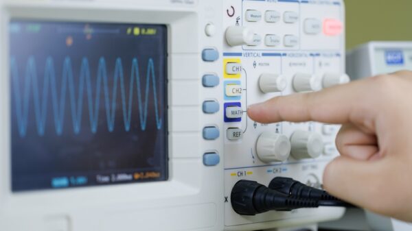
Setting up the oscilloscope
To properly test a servo motor, technicians must carefully configure the oscilloscope. This requires expertise in:
- Probe Selection: Use appropriate voltage and current probes. For high-frequency measurements, differential probes may be necessary to reduce noise.
- Bandwidth: Ensure the oscilloscope has sufficient bandwidth to capture high-frequency components of the motor signals —at least 100 MHz for most servo motor applications.
- Sampling Rate: Set a high enough sampling rate to accurately capture rapid signal changes, especially for PWM signals.
- Triggering: Configure proper triggering to stabilize the waveform display and capture specific events of interest.
- Math Functions: Utilize built-in math functions for tasks like calculating power consumption or analyzing harmonics.
Advanced analysis techniques
Modern digital oscilloscopes offer advanced features that significantly enhance servo motor testing capabilities. For example, Fast Fourier Transform (FFT) analysis can reveal frequency components in motor signals, helping identify sources of noise or vibration. Likewise, XY mode plotting of current against back EMF provides insights into the motor’s efficiency and power factor. Other built-in automated measurement functions can streamline the quantification of key parameters, making the testing process more efficient and repeatable.
Interpreting results based on critical data points
Oscilloscopes are powerful tools for testing and optimizing servo motor performance. By providing detailed, real-time insights into electrical and mechanical behavior, they enable engineers to identify issues, validate designs, and ensure reliable operation.
Key indicators of motor health and performance include smooth, symmetrical current waveforms, consistent back EMF amplitude across all phases, accurate and noise-free position feedback signals, stable PWM signals (with expected duty cycles), and minimal high-frequency noise or unexpected harmonics. Any deviations from expected patterns may indicate issues that require further investigation or corrective action.
Test regularly to stay abreast of emergent servo motor problems — before they become production headaches! If your equipment needs testing or maintenance, count on GES. This September, we’re offering 15% OFF repairs for three or more servo motors or 10% OFF on any single servo motor repair.