Looking Closer at Rotor Bar Cracks in Induction Motors
When an induction motor begins to lose torque or run less efficiently, the cause often lies deep within the rotor cage. Rotor bar cracks are among the most revealing forms of internal damage. They offer visible evidence of stress, imbalance, or fatigue that has developed over time. Where these cracks occur and how they propagate can help technicians trace faults back to the forces that created them.
Forces behind rotor bar cracking
Rotor bars endure a combination of mechanical, thermal, and electromagnetic stress during every operating cycle. Over time, these conditions weaken the conductive elements that carry current and generate torque.
- Thermal stress develops from repeated startup surges. High inrush current expands and contracts the rotor metals, especially at the joints between bars and end rings.
- Mechanical stress builds as centrifugal forces act on the rotor at full speed, pulling against the bar shoulders and end rings.
- Electromagnetic stress arises from uneven magnetic flux or load imbalance, concentrating current in specific regions of the rotor cage.
Operating conditions often amplify these forces. Frequent starts and stops accelerate fatigue, while unbalanced loads and poor cooling create local temperature gradients that intensify cracking. The interplay of these stresses defines the pattern and direction of damage observed during teardown.
What the crack location reveals
The physical location of a crack provides critical diagnostic insight. Each region of the rotor is susceptible to a distinct failure mode:
- Bar ends: Cracks near the bar-to-end-ring junction typically originate from thermal expansion mismatch. As the rotor heats and cools, the rigid connection between dissimilar metals concentrates stress where they meet. High-duty-cycle applications or motors that start frequently tend to show this pattern first.
- Along the bar length: Longitudinal fractures usually indicate mechanical vibration or load imbalance. Misalignment or unbalanced torque creates alternating stress along the bar’s body, producing fatigue lines parallel to its axis. These cracks can remain subsurfaced for long periods, gradually deepening.
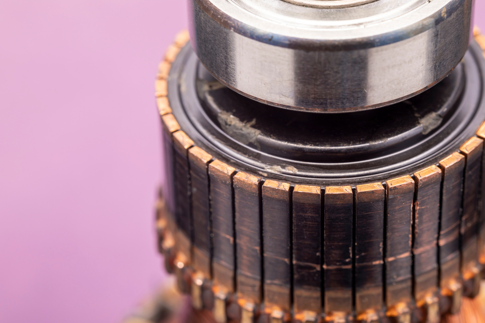
- At slot shoulders or corners: The slot edges where the bar meets the laminations act as natural stress risers. Cracks in this area often point to slot looseness or wear between the bar and core material. Over time, vibration can cause fretting between components, eroding insulation and altering the magnetic circuit. If left unchecked, this type of damage can spread into the lamination stack.
Identifying which region fails first helps determine whether the problem stems from electrical design, mechanical alignment, or operational conditions.
Connecting evidence to the cause
During an inspection, the position and geometry of cracks guide technicians toward the underlying failure mechanism.
- Bar-end cracking suggests thermal cycling from high startup current or inadequate cooling.
- Mid-bar cracking points to vibration, shaft misalignment, or rotor unbalance.
- Slot-edge cracking calls for checking core integrity and slot fitment tolerances.
Each diagnosis shapes the next maintenance step. Replacing damaged bars restores function, but addressing the stress that caused the failure — whether electrical, thermal, or mechanical — prevents recurrence. Non-destructive testing, such as eddy-current or magnetic-particle inspection, confirms the extent of internal propagation before reassembly.
Reading the evidence in metal
Rotor bar cracks tell the story of how a motor has operated under load — where it ran hot, where it flexed, and where its materials reached their limits. Learning to interpret those signs transforms a simple teardown into an opportunity to understand system stress. Each fracture represents a cause, not just a symptom. Reading them correctly turns failure analysis into a foundation for improved motor performance and longevity.