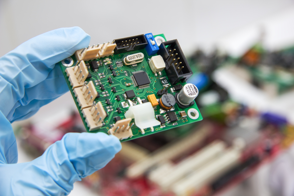
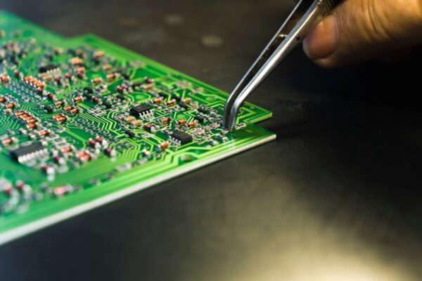
How to Identify and Repair Common Control Board Issues

Control boards cause some of the most frustrating failures in industrial equipment. They tend to create mysterious behaviors that seem to come from everywhere else in the system. Random resets, phantom inputs, delayed responses, and persistent nuisance faults all point to software or wiring issues — until you discover the real culprit is a $2 capacitor on the logic board.
The challenge with control board failures is that they degrade slowly, creating intermittent problems that are nearly impossible to replicate during testing. Here’s a systematic approach to identifying and fixing these elusive issues.
Step 1: Look beyond the power-on test
Just because the board powers up and the status LEDs look normal doesn’t mean it’s functioning properly. Random resets or intermittent booting often point to unstable voltage regulation caused by aging capacitors or damaged power rails. Watch for systems that appear to lock up without clear fault messages — this typically indicates timing errors from overheated chips or poor solder joints rather than programming issues.
Pay attention to phantom inputs or missed outputs that scramble signal paths without leaving visible damage. These symptoms suggest corroded traces or failing microcontrollers that pass basic functionality tests but fail under real operating conditions.
Step 2: Identify environmental damage patterns
Control boards don’t just fail—they degrade over time due to environmental factors. Dust buildup around high-voltage areas becomes conductive in humid conditions, leading to arcing, tracking, or degraded insulation that causes unpredictable behavior. Heat cycling near power transistors creates repeated expansion and contraction that weakens solder joints and delaminates internal layers.
Look for vibration stress near edge connectors, especially on boards installed near moving equipment. These often develop microcracks around pins and mounting points that create intermittent connections. Chemical exposure from nearby oils, vapors, or cleaning agents can corrode traces and protective coatings, accelerating component degradation.
Step 3: Perform dynamic testing under load
Move beyond simple continuity checks to testing that re-creates actual operating conditions. Check for bulging capacitors, burnt areas, or lifted pads that indicate where damage started. But don’t stop there! Measure voltage at multiple test points while the system is running under load — fluctuations or dropouts often appear during operation that won’t show up during startup testing.
Use thermal imaging during runtime to identify overheated chips or resistors that appear as hot spots, revealing where the board is under stress. Probe traces and solder joints with an oscilloscope or meter to find cold solder, cracked vias, and poor grounding connections that seem normal during visual inspection.

Step 4: Evaluate repair vs. replacement options
Not every damaged control board needs complete replacement — many can be salvaged with the right approach. Replace failed capacitors, regulators, or optoisolators that commonly fail first and can usually be swapped without major rework. Consider reflowing solder joints or rebuilding damaged traces using micro soldering techniques and proper solder mask application.
Remember to verify part compatibility before substituting components, since one incorrect value or mismatched rating can disrupt the entire feedback chain. Always test repairs under actual system load rather than relying on bench testing, since runtime behavior provides the final validation of repair success.
Step 5: Address root causes to prevent repeat failures
Focus on eliminating the conditions that caused the original failure rather than just fixing the immediate problem. Improve ventilation or heat dissipation around components that showed thermal stress during testing. Clean dust and debris from critical areas and seal against future contamination (where possible).
Secure mounting points and reduce vibration exposure to prevent future mechanical stress on solder joints and connectors. Document the failure mode, environmental conditions, and repair steps taken — this information becomes invaluable for preventing similar failures and improving maintenance across similar equipment.
The silent problems need the loudest attention
Control board failures excel at hiding behind other symptoms, creating diagnostic challenges that waste time and resources. The key to success lies in systematic testing that goes beyond surface-level checks to understand how components behave under real operating conditions.
Need a hand getting to the bottom of a troublesome control board issue? Now through the end of the month, GES is offering 10% OFF single repairs or 15% OFF 3+ repairs on safety equipment!
