Motor Control PCBs: A Brief Functional Overview
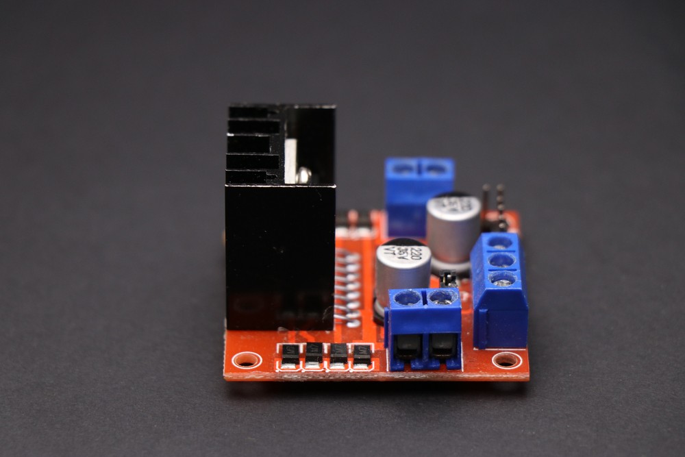
Motor control printed circuit boards (PCBs) are the primary regulators for electronic motor function. They dictate how a motor performs within specific parameters and allow operators to make adjustments based on the task at hand. In short, PCBs control the function of a motor. When faults develop, they affect the controller’s efficacy and present hazards for operators and equipment alike.
Here’s a closer look at motor control PCBs, the different types, how they work, and the common reasons they develop faults.
Types of motor controllers
There are several distinct types of motor controllers for different degrees of precision control over motor function. Some of the most prevalent for applications across the industrial manufacturing sector include:
- Activators. These controllers activate the power supply to motors, and when necessary, stop and start the drive based on predefined parameters.
- Variable speed drive. These devices allow operators to set a desired operating speed, either automatically or manually.
- Servo controllers. These motor controllers handle advanced features — such as speed control and speeding up at an accelerated rate — better than other types.
- Intelligent controllers. These “smart” controllers adjust the rotating force of a motor based on load measurements.
The more complex a motor’s control PCB unit, the more it’s capable of regulating. But this complexity also means these units are prone to fault and failure. Understanding the types of motor controllers can help manufacturers choose the right ones for a specific application — and recognize the signs of an impending failure.

Variables controlled by the PCB
Technicians can operate PCBs remotely, automatically, or manually. These devices have other functions besides activating and deactivating a motor. The PCB is basically the “brain” of the motor. It dictates control over many important functional and operational variables, including voltage, speed, current and position.
PCBs can safely manage all these variables when functioning properly, but when problems arise, they can quickly affect motor function and performance. At best, it leads to inefficiency. At worst, it becomes a safety hazard. For this reason, it’s essential to understand the common reasons for PCB failure and how best to prevent them.
Common reasons for motor controller failure
Though PCBs are smart and essential, they’re prone to faults and problems that affect motor operation. PCBs can feature hundreds of different components — and even one damaged component can cause complete failure. Common issues with PCBs include:
- Improper calibration
- Component contamination
- Excessive vibration
- External input failure
- Overheating
- Overcooling
- Inadequate component quality
A good understanding of how PCBs work allows technicians to identify and repair issues before they cause major damage. Like all critical components, PCBs require proper installation and routine maintenance to perform at maximum efficiency.
Motor controllers are a vital component
Without a well-functioning motor control PCB, it’s impossible to operate an electronic motor with any real control. At best, it’s inconsistent; at worst, it’s dangerous. In the event of a faulty PCB, make sure you’re working with a qualified technician to troubleshoot and remediate the problem — or replace the PCB altogether. The safe, efficient function of your motor depends on it.